 |
|
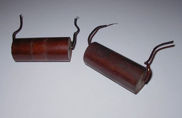
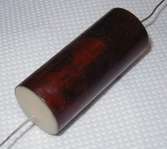
Fig. 1: Original (Philips) 4uF electrolytic capacitors from a Hornyphon DKE38 |
Renovating the electrolytic capacitors of your DKE38
|
|
|
Fig. 1: Original (Philips) 4uF electrolytic capacitors from a Hornyphon DKE38 |
The 4uF electrolytic capacitors originally fitted to a DKE38 will almost certainly have dried up by now and will need replacing. If you switch a DKE38 on with faulty electrolytics fitted you run the risk of destroying your VY2 rectifier valve. Renovating the capacitors is MUCH easier and cheaper than sourcing a new VY2!!! This article is a step-by-step guide to giving your DKE38 electrolytics a new and long lease of life.
Before proceeding please read IMPORTANT MESSAGE at the bottom of the page.
The best plan is to remove the 'guts' of the old capacitors and fit new capacitors inside the old sleeves. Done sympathetically this gives a very satisfactory result which is difficult to distinguish from the original.
STEP 1: Removing the chassis from the cabinet
WARNING: SWITCH OFF AND DISCONNECT FROM THE MAINS SUPPLY BEFORE PROCEEDING
Remove the two small round bakelite knobs from the front of the radio (grub screw, slot head screwdriver).
Remove the back panel (four slot head screws with washers).
Unsolder the two speaker wires at the speaker end.
Remove the two chassis mounting screws and angle washers.
Carefully slide the paxolin chassis out of the cabinet.
STEP 2: Removing the old capacitors from your radio
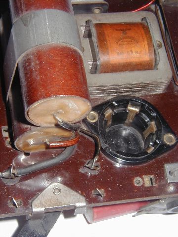
Carefully note the position, fixing and wiring of the two electrolytic capacitors. It is strongly recommended that you take photographs of the wiring arrangement or at least make a sketch. Take particular note of the polarities of the two capacitors. The positive end is marked on the outer sleeve. The two photographs below show the arrangement of the metal strap that secures the capacitors to the paxolin chassis.
 |
|
Fig. 2: capacitor fixing arrangement - top view |
 |
|
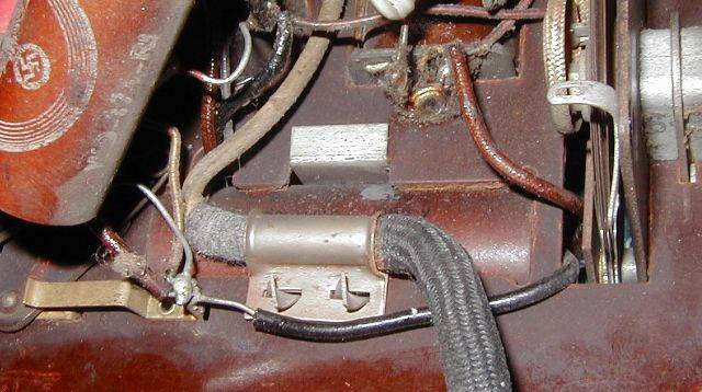
Fig. 3: capacitor fixing arrangement - bottom view showing twist tabs and cable restraint feature |
The capacitor fixing is in two parts. On the topside is a metal strap that fits snugly over the capacitors. On the underside is a clamp plate which doubles as the mains cable restraint. One end of the strap hooks into a slot in the chassis, whilst the other end has two tabs which fit through the clamp plate and are twisted to secure. Carefully bend the two twist tabs so that they align with the slots in the clamp plate. Do this carefully to avoid breaking the tabs off. The metal (steel) is quite tough so you will need to use a strong pair of pliers. You should now be able to separate the strap from the fixing plate. This is a fiddly job, but not as fiddly as putting it all back together!
STEP 3: Removing the innards of the old capacitors
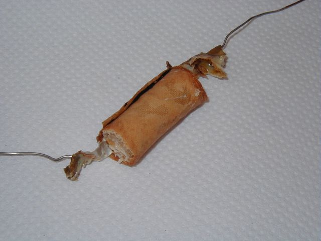
The ends of the capacitors are sealed with pitch. I have seen black, brown and off-white coloured pitch but it all seems much the same sort of stuff. To remove the pitch place the capacitors in a suitable heat resisting tray (e.g. an aluminium pie dish) supported such that the pitch can run out without running over the outside of the capacitor sleeves. Place the capacitors in an oven at approximately 180 deg C and watch for the pitch melting. Remove the capacitors as soon as most of the pitch has run out. Using a cloth to protect your hand, push the 'guts' of the old capacitors out with a pencil or similar. Try and remove as much as you can of the pitch whilst it is still malleable. The Fig. 4 below shows typical innards of the old capacitor, although they do vary. Discard the innards.
 |
|
Fig. 4: typical innards of the old capacitor |
Allow the empty sleeves to cool and then clean them up using white spirit (turpentine substitute) sparingly. The capacitors I have renovated have retained their markings when rubbed with white spirit but it's worth being cautious. Allow the cleaned up sleeves to dry.
STEP 4: Fitting the new capacitors into the sleeves
Obtain two 4.7uF 450V DC WKG electrolytic capacitors. These can be axial or radial leaded but you need to choose capacitors with adequate ripple current rating. A rule of thumb is that the ripple current rating should be at least twice the HT current drawn by the radio. For a DKE38 a capacitor with a minimum ripple current rating of 50mA should suffice. A suitable capacitor is available from RS ( http://rswww.com ) part number 228-7287. This RS part has a ripple current rating of 79mA (at 120Hz, 85 deg.C).
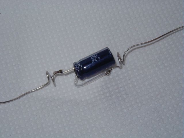
Solder 0.9mm dia. tinned copper wire terminations to the new capacitor as shown in Fig. 5 below. Allow a generous length for these terminations, using the original sleeving as a guide. The wires from the capacitor are shown sleeved with a clear PTFE sleeving. This is not absolutely necessary but does eliminate worries about the two lead-out wires shorting together. The lead-out wires have been given a single turn to act as a strain relief. The distance between these two lead-out turns must be approx. 12mm less than the length of the original capacitor sleeve.
 |
|
Fig. 5: connecting tinned copper wires to the new capacitor |
Cut a strip of thin corrugated cardboard, slightly wider than the capacitor body length and wrap it around the new capacitor as shown in Fig. 6 below. The roll should be a snug fit in the original capacitor sleeve. Note which end is positive.
 |
|
Fig. 6: thin corrugated cardboard wrapped around the new capacitor |
Fit the roll into the original sleeve so that the assembly is central within the length of the sleeve. Make certain that you fit it so that the positive wire of the new capacitor aligns with the '+' end of the old sleeve. Stuff cotton wool into the open ends of the assembly to within a couple of millimetres of the ends.
STEP 5: Sealing the ends
The ends must now be sealed. If you managed to save the original pitch then you should be able to re-use this. However, I prefer to use wax. In the UK I can get a wax that is used for restoring furniture. It is made by Liberon and comes in different shades from white through various shades of brown to ebony black. It is a bit on the soft side but seems to be OK for this purpose. An alternative, which I haven't actually tried, would be to melt a shellac stick (again available in various shades from Liberon and obtainable from furniture restorers). If using wax proceed as follows:
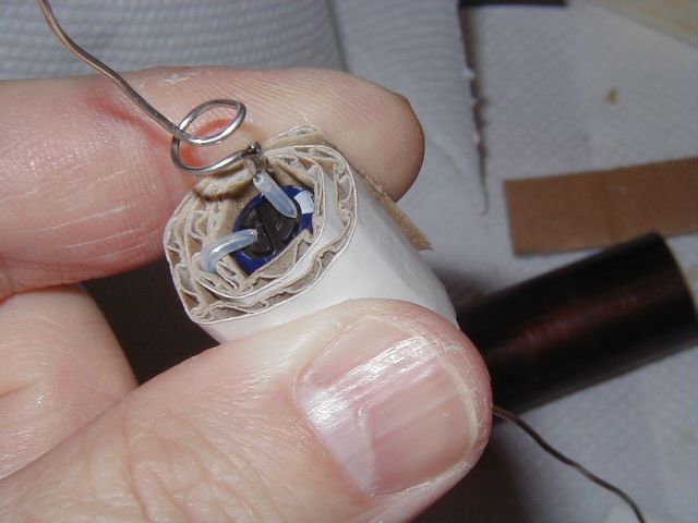
Hold the capacitor assembly vertically as shown in Fig. 7 below and slowly melt the wax so that it saturates the cotton wool. I use a soldering iron to melt the wax.
 |
|
Fig. 7: filling with wax |
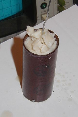
Once the cotton wool is saturated, allow it harden. Whilst waiting for it to harden, use the time to saturate the cotton wool at the other end. Once the first layer of wax has hardened, you can proceed by placing a few wax chips into the void and carefully melting these to fill the end. Only fill a small amount at a time and allow it to harden. Alternate the end being filled to allow cooling time. The trick is to keep the top layer molten and the lower layers solid. If you apply too much heat over too long a period the whole lot may melt and drip right through the sleeve. Fig. 8 shows one end awaiting the final layer.
 |
|
Fig. 8: one end awaiting the final wax layer |
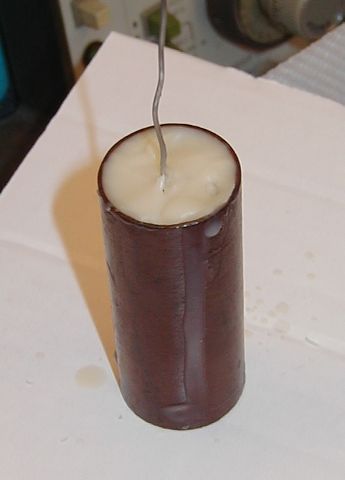
Once the void is full, give a final surface melt and allow to harden to a nice smooth surface. Clean any wax overspill from the outside of the sleeve. The finished end should look as in Fig. 9 below.
 |
|
Fig. 9: the finished capacitor |
STEP 6: Refitting the capacitors to your radio
Fit the original sleeving to your renovated capacitors. The sketches/photo's and notes you took at the start of the project should enable you to fit the original sleeving properly. Bend the wires to approximately the same shape as in the original. Cut the lead out wires to manageable lengths.
Now is a convenient time to replace the mains cable on your set if you want to. The old rubber wire has often perished and become dangerous. Simply pry open the clamp plate sufficient to remove the old cable and then fit a new one.
Fit the capacitors to the chassis, making sure that the leadout wires follow their original courses and that the polarities are correct. Refit the strap and clamp plate and twist the twist tabs to secure, taking care not to break off the tabs. As noted earlier, this is quite a tricky 'juggling act' and a degree of patience and some dexterity is required. The finished assembly should be a nice snug fit. The capacitors should be firmly held in place. Take care not to deface the nicely finished wax ends. Before soldering the connections double check polarities.
After soldering the lead out wires to their original tags, the job is finished. Refitting the chassis to the cabinet is the reverse of it's removal.
The above information is offered in good faith and is based on my experiences with several different makes of DKE38. However you use this information entirely at your own risk. Please note that I accept no responsibility for any injury, damage or loss-of-value howsoever caused.
![]()
![]()
Copyright Ó 2002 Lorne Clark