 |
|
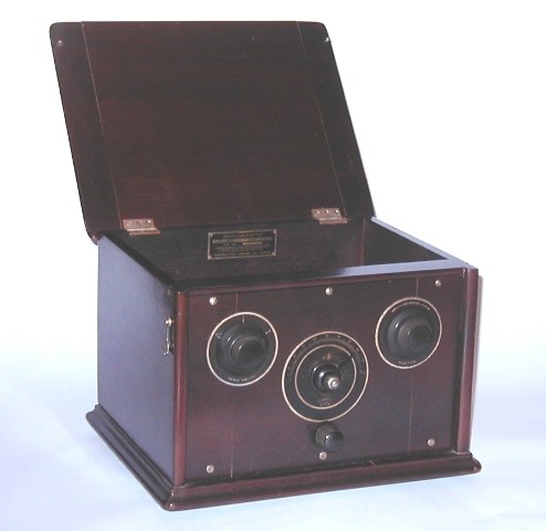
Fig. 1: Marconiphone Type 22 receiver |
vintage radio wireless valve museum tube vintage marconiphone type 22 DER radio aerial antenna reaction unit
|
|
|
Fig. 1: Marconiphone Type 22 receiver |
This is the Marconiphone Type 22 two valve TRF* set manufactured in 1927 by Marconi's Wireless Telegraphy Co, Ltd. The instrument is housed in a polished mahogany cabinet with lift up lid bearing the Marconi logo.
*Tuned Radio Frequency
The following picture shows a general interior view:
 |
|
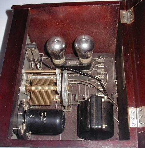
Fig. 2: Marconiphone Type 22 receiver interior view |
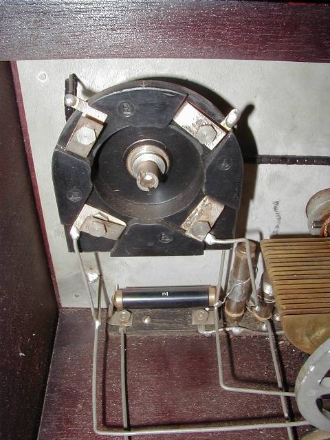
Major components shown in Fig. 2, clockwise from top left are as follows:
5 pole 3 position 'RANGE' switch
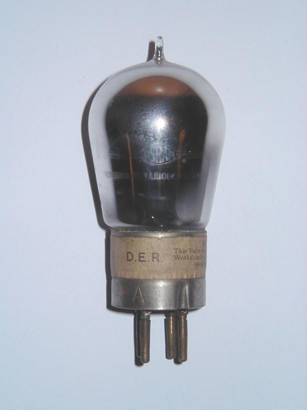
Detector valve (type 'DER' shown) on shared anti-microphony mount
AF output valve (type 'DER' shown) on shared anti-microphony mount
Terminal strip (for battery connections)
AF coupling transformer
'AERIAL REACTION' unit
Variable 'TUNING' capacitor
Aerial, Earth and headphone connections are made to binding posts at the rear of the set.
The circuit diagram of the set is reproduced below:
|
|
|
Fig. 3: circuits reproduced from 'Vintage Radio Service Data Vol. 2' with the kind permission of Paul Stenning http://www.vintage-radio.com |
Circuit Operation
The 5 pole 'RANGE' switch has 3 positions. In the 'OFF' position the LT and HT1 supplies are disconnected and the aerial (antenna) is earthed (preventing static build-up). For positions 1 and 2 the LT and HT1 supplies are connected, thus turning the set on.
The choice between 'RANGE' switch position 1 or 2 depends upon the length of aerial used. Position 1 is selected for medium length aerials (approx. 50 feet) and position 2 for short aerials (less than 50 feet). The 0.0005uF variable capacitor (front panel tuning control) and the tapped aerial tuning coil form a variable tuned circuit. The output from this tuned circuit is connected via the 0.00025uF capacitor to the grid-leak detector comprising V1 and the 1M grid leak resistance.
The output from the detector anode contains the recovered audio signal and a certain amount of modulated RF as well. This RF output is fed back to the aerial tuner via the reaction winding adjacent to the tapped aerial tuner inductance. The fed-back signal has the correct phase needed to achieve positive feedback. The strength of the fed-back signal, and thereby selectivity of the receiver, is adjustable by means the 'REACTION' control which varies the coupling between the tuning and reaction windings. The audio output from the detector is connected to the primary of the 4:1 LF interstage coupling transformer. The 'OS' output from the secondary of the coupling transformer is connected to the grid of the LF amplifier V2. V2 receives its grid bias via the lower secondary terminal. The headphones are connected between the anode of V2 and HT2.
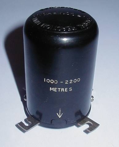
The aerial tuning and reaction coils are contained within a plug-in 'AERIAL REACTION' unit, an example of which is shown below:
 |
|
Fig. 4: Plug-in 'AERIAL REACTION' unit |
 |
|
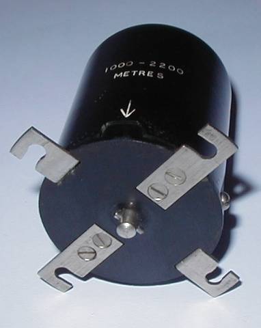
Fig. 5: Plug-in 'AERIAL REACTION' unit, bottom view |
 |
|
Fig. 6: Plug-in 'AERIAL REACTION' unit open |
Connections to this plug-in unit are via the Aerial Reaction Unit Adaptor shown below:
 |
|
Fig. 7: Plug-in Aerial Reaction Unit Adaptor |
'AERIAL REACTION' unit
The 'AERIAL REACTION' unit, Fig. 4, attaches to the adaptor, Fig. 7, with a push and twist bayonet action. The tapped aerial tuning inductance is the larger (fixed) coil shown in Fig. 6. The smaller concentric coil is the reaction winding. This reaction winding is fixed to the shaft that protrudes from the base of the unit (Fig. 5) and is free to rotate relative to the fixed coil. This allows the mutual coupling between the two windings to be varied in response to shaft rotation. The drive shaft & pin on the base of the unit engages with the notched shaft on the adaptor. As the front panel 'REACTION' control is rotated the drive is transmitted through the shafts to the central rotating reaction coil assembly within the unit, Fig. 6.
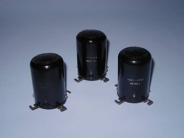
Several different 'AERIAL REACTION' units were available to cover the various broadcast wavelengths and a selection covering the bands 350 metres to 2200 metres are shown below:
 |
|
Fig. 8: Selection of plug-in Aerial Reaction Units: 350m to 2200m |
Power Supplies
External LT, grid bias and HT supplies are required. These could be provided by batteries or a mains driven battery-eliminators. Two battery eliminators were available from the manufacturers: the DC1 was designed for use with DC mains supplies and the AC1 was designed for AC mains supplies. The AC1 supply provided AC heater current and so the user would need to select one of the (then) newly available indirectly heated valves specifically designed for use with AC heater supplies.
VALVES
For use with batteries or the DC1 supply the set might well have been fitted with Marconi-Osram 'DER' valves which required 1.8V at 0.4A for the filament. When using the AC1 supply the set might well have been fitted with the new KH1 (V1) and KL1 (V2) indirectly heated valves introduced by Marconi-Osram in January 1927. To overcome a limitation of the then common 4-pin English valveholder, these indirectly heated valves had the cathode connected to a terminal on the side of the bakelite base. This is why the AC1 supply has spade terminal connections for the cathodes.
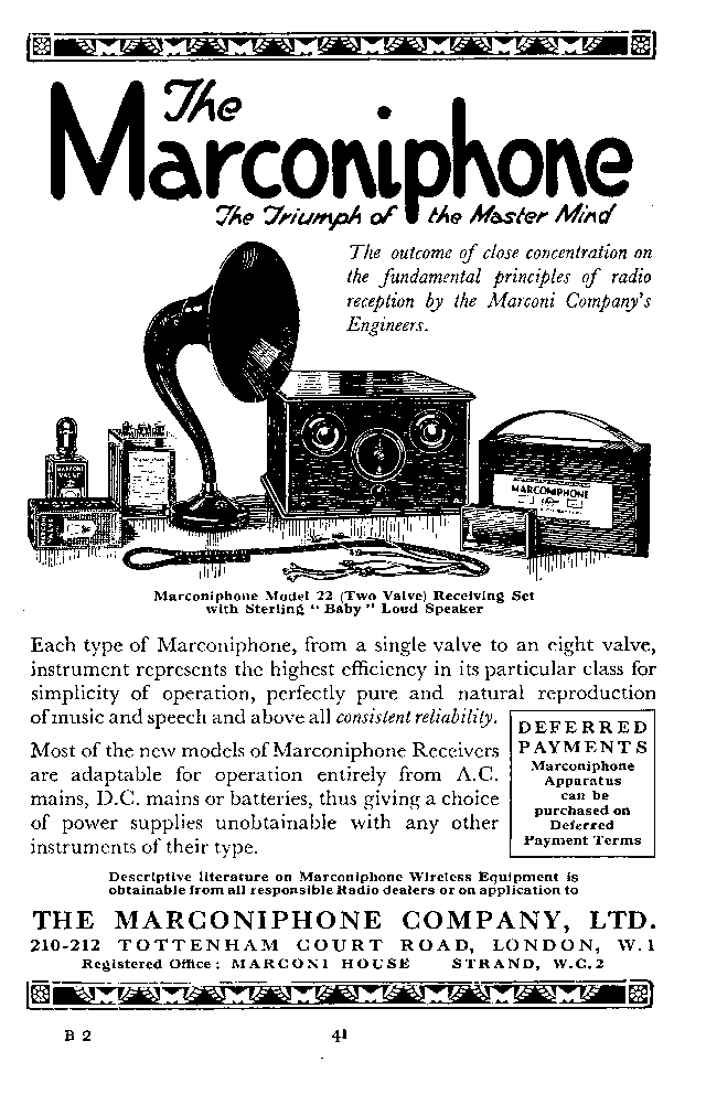
Advertisement
Here is a period advertisement for the Marconiphone Type 22 set:
|
|
|
Period advertisement placed in the 'BBC Handbook 1928' |
![]()
![]()
Copyright Ó 2002 Lorne Clark