|
|
Renovating the electrolytic capacitors of your DKE38
click the picture |
deutscher kleinempfanger dke38 schaub vintage radio wireless trf vcl11 vy2 tetrode schaub museum vintage
|
|
Renovating the electrolytic capacitors of your DKE38
click the picture |
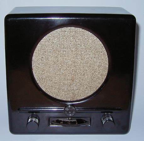
This is the Deutscher Kleinempfänger DKE38 made by G. Schaub in Germany around 1938. It is a 1 valve (plus rectifier) mains TRF housed in a dark brown bakelite cabinet subtly speckled with other colours.
Deutscher Kleinempfänger means 'German small receiver' in English, and the DKE38 was in fact a low cost peoples-set designed for mass production and intended to be introduced into as many German homes as possible. Otherwise known as Goebbels Schnauze (Goebbels' gob) it was intended primarily for the communication of German propaganda and was manufactured by a number of manufacturers. Follow this link to hear Heir Goebbels promulgating some radio production facts and figures: Goebbels. Somewhat low on entertainment value, but historically interesting nonetheless.
Its design is simple and whilst it would have been adequate for receiving strong local stations, it would have required a good aerial, a deal of patience and good hearing to have picked up much else. Many of the parts used in this set (cabinet, valves, transformers, loudspeaker, chassis etc.) were marked with the German Reichsadler.
The circuit diagram for the set is shown below:

This contemporary circuit is drawn in a way that makes it somewhat difficult to see what is going on. This seems to be a direct result of the obsession some draughtsmen had with trying to convey spatial pin-out information within the valve symbols! Surely it's better to make the circuit easy to understand and deal with the pin-out elsewhere.
Anyway, the aerial tuning circuit comprises RF transformer 2, 3, 4, 5, 6 and tuning capacitor 8. Three connections are made to the primary of the RF transformer to cater for aerials if different lengths. The primary is mounted on a swinging arm by which means the degree of coupling between the primary and secondary may be adjusted via a front panel control. The switch in series with 5, 6 is ganged with tuning capacitor 8. The edgewise tuning scale attached to tuning capacitor 8 is marked in degrees and has a MW section and a LW section. When the scale is rotated into the LW section, the switch opens to increase the inductance and hence the resonant wavelength. Capacitor 15 couples the AM signal to the grid of the triode section of the VCL11. This triode is wired as a detector of the grid-leak type, resistor 9 (1M Ohm) providing the 'leak'. The output from the anode of the triode detector contains both audio and modulated RF. The audio is coupled via capacitor 12 and resistor 13 to the control grid of the tetrode section of the VCL11 whilst the RF portion is coupled to the reaction control circuit comprising capacitors 10 & 11 and RF transformer winding 7. Capacitor 10 provides front panel adjustment of the strength of reaction (positive feedback) and hence the degree of selectivity/sensitivity. grid bias for the tetrode control grid is provided by resistor 14 coupled to the right hand side of variable resistor 22. The cathode of the tetrode is connected to the left hand side of resistor 22 and this resistor is used to 'buck-out' residual line-frequency hum (a small residual line-frequency hum voltage will appear across resistor 22 and this is used to cancel hum introduced elsewhere). The screen grid of the tetrode connects to +195V whilst the anode is connected to one side of the reed loudspeaker with the other side also going to +195V. Resistor 16 (2 M Ohm) and capacitor 17 (30pF) are thought to introduce a degree of negative feedback to reduce AF distortion.
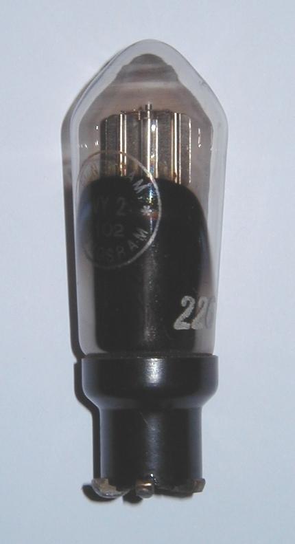
Incoming line voltage is connected via a DP switch operated from the back panel. A fuse 27 is connected in series with one pole of this switch. An adjustable mains-dropper resistor 26 is connected in series with the series valve heaters. The half wave rectifier VY2 rectifies the raw mains voltage and delivers DC to the smoothing circuit comprising choke 20 and electrolytic capacitors 23 and 24. These electrolytics are often dried out and will probably need replacing. BEWARE, a shorted electrolytic will destroy the rare VY2 rectifier! Follow the link at the top of the page to see how to renovate the electrolytics. Capacitor 25 is an RF filter and capacitor 21 filters out the higher order line harmonics that would otherwise be developed across the hum-bucking resistor 22.
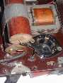
The placement of the 'topside' components is shown below:

![]()
![]()
Copyright Ó 2000 - 2002 Lorne Clark