 |
popular wireless crystal experimenter's experimenters handboob vintage radio wireless crystal set valve museum boatanchor tube aerial antenna tester 2LO vintage marconi gecophone detector galena perikon cat's whisker germanium gec junior no.1 western electric counterpoise mighty atom modern magic carpet
This page gives an insight into the wondrous world of crystal sets. Here you will find theoretical details of how a crystal set works and the types of components used. You will also find details of how to build a working set for yourself. You may have nostalgic recollections of a crystal set that you owned or built in your youth or you may simply have heard of such radios and wondered what they are all about; either way you will find something of interest here. The more advanced reader may be interested in the Popular Wireless 'Crystal Experimenter's Handbook' section below.
A crystal set is the simplest form of AM (amplitude modulation) receiver yet devised. It costs little to build, has great potential for experimentation and usually requires no source of power for its operation other than the radio signal itself. Does this sound too good to be true? Not at all. YOU can build one easily and cheaply and I'm sure the results will impress. It will certainly give immense satisfaction.
Crystal sets date back to the earliest days of wireless (pre-W.W. I) and an enormous variety of circuit designs and cabinet styles have been produced over the years. Their popularity has been variable as developments in other more elaborate forms of reception have taken place. However peoples fascination with this simplest form of reception is enduring and remains strong to this day.
To answer this you need to first understand a bit about the AM signal that is sent out from the transmitter.
An AM transmitter sends out its broadcast in the form of an electromagnetic wave that radiates from its aerial (antenna). With no sound content in the programme, the wave is a constant amplitude 'carrier wave', who's frequency is as shown on the dial of an AM radio (also sometimes shown as its wavelength). The strength, or amplitude, of these waves is made to vary in response to the audio content of the programme. The resulting wave is called an amplitude modulated wave. The following diagram shows how such a wave would look if you could view its change in amplitude with time:
 |
The purpose of a simple AM receiver is to pick up these AM waves and extract the audio signal so that it can be heard by the listener. It does this by a process called 'detection'. The detection process utilizes a device called a detector which effectively strips off either the upper half or lower half of the AM wave. It only remains to filter out the carrier wave to leave the audio signal and the job is done! The following diagram shows how the detector and filter work together to 'recover' the original audio signal:
 |
The strength of the recovered audio signal is small but, given the right conditions, it can be large enough to drive a pair of headphones; all without any power source other than the signal itself. Amazing.
In its VERY simplest form, a crystal set receiver comprises just four main elements:
1. A good aerial (antenna) and earth
2. A detector
3. A filter capacitor (Cf)
4. An earpiece or headphones
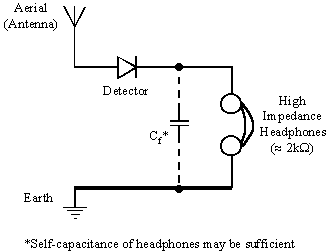
These can combined to form the most basic circuit, such as shown below:
 |
|
Fig. 1 - Most basic crystal set |
The aerial consists of a length of wire suspended above the ground, whilst the earth may be a metal spike driven into the ground. An AM broadcast will set up an alternating voltage between the aerial and the earth. This voltage will cause an alternating current to flow around any circuit connected between the aerial and earth. Thus an alternating current due to the AM broadcast will try to flow through the detector. Since current can only flow in one direction through the detector, the other half of the alternating current is blocked. The remaining uni-directional current is filtered by the combined effect of the headphone impedance and the capacitor and only the audio signal current passes through the headphones.
One drawback with the very simple circuit shown above is that it has little or no selectivity. That is, it picks up all AM broadcast signals with similar efficiency. Some sort of tuning is required so that we can select just the broadcast we want. The following circuit has tuning components added:
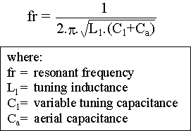
When a capacitor is connected in parallel with an inductor and an alternating voltage applied across the combination, alternating current will flow. The amount of current that flows depends upon the frequency of the applied voltage. At a particular frequency, called the resonant frequency, almost no current flows. For frequencies above or below the resonant frequency, significant current will flow. In Fig. 2, C1 plus the aerial capacitance forms the capacitor of our tuned circuit, whilst L1 forms the inductor. At the resonant frequency of the tuned circuit, almost no current flows to earth through L1 or C1, leaving virtually all of it free to flow through the detector. Alternating currents at broadcast frequencies either above or below the resonant frequency will tend to flow through C1 or L1 to earth. Thus we have added selectivity to the receiver. Notice that C1 is adjustable, as signified by the arrow. By varying C1 we can tune the receiver to select specific broadcast frequencies.
The equation that relates (approximately) the resonant frequency to the values of parallel capacitance and inductance is as follows:
 |
There are still a number of drawbacks with the arrangement of Fig. 2:
1. The aerial forms a significant part of the total tuning capacitance and so the tuning range available by varying C1 will be small
2. A consequence of the aerial capacitance is that the upper frequency that can be tuned is quite limited.
3. The circuit is not particularly efficient and tuning will be quite 'flat'.
4. The detector also adds capacitance and it's loading effect worsens efficiency
We shall return to circuit topology later to see what improvements can be made but first a bit more on 'the basics'. To skip this and move straight to details of an improved design that you can easily build click HERE. To return to this page please use the 'back' button on your browser.
The main requirement for a detector is that it should act as a non-return 'valve' to the alternating currents of the AM wave. If you could look at the alternating current in a circuit you would see it flowing back and forth, first one way and then the other. A detector placed in such a circuit allows the alternating current to flow easily in one direction but not in the other. Certain naturally occurring minerals were found to have this property and these became some of the earliest forms of detector. One such mineral, the crystalline form of galena (lead sulphide), was found to be particularly good at detection, and became very popular. The following photograph shows a fine piece of galena in its original tin. Also shown in the photograph is the 'cat's whisker' (the small coil of wire) which was used to make contact with the crystal.
In use, the crystal was held securely in a metal holder whilst the 'cat's whisker' was held in another small holder to which was attached a handle. The photograph below shows such an arrangement, as used on the GECoPHONE No. 1 crystal set:
The holder carrying the crystal forms one electrical contact whilst the holder carrying the cat's whisker forms the other contact. In use, it was necessary to carefully adjust the cat's whisker until contact was made with one of the numerous contact sites covering the surface of the crystal. Not all these contact sites are equally sensitive, and some experimentation is required to find the 'sweet spot'. Unfortunately the adjustment is not very stable and a slight knock or vibration could easily cause contact to be lost. For this reason it was not used in receivers likely to encounter rough use (e.g. military receivers).
Many other types of detector were found in the early days of radio. Here is an extract from an excellent book 'Wireless The Modern Magic Carpet' by Ralph Stranger*, Pub. Partridge, London 1928. Chapter XI entitled 'Crystals' is an interesting insight into early work on solid state physics. The material may also be of value to those experimenting with different types of crystal detector. To download or view this pdf file (603KB) click on the image of the book below. Note that to view this file you will need Adobe Reader version 5.0 or later. To get Adobe Reader (entirely free) please click on the link near the bottom of this page.
*real name: Ralph Judson, a Russian-born engineer who joined the BBC in 1925, eventually becoming Advertisement Manager. He wrote many useful and highly readable books. I have a copy of 'Wireless the Modern Magic Carpet' signed by the author.
Some of these materials were used by manufacturers to construct what were termed 'permanent' detectors, i.e. detectors that required no adjustment. These must have been most attractive to the home constructor. Today more modern forms of permanent detector suitable for crystal sets are available, using a processed version of the mineral Germanium as the means of detection.
Popular Wireless 'Crystal Experimenter's Handbook'
If you are really keen on finding out just what can be achieved using crystal and mineral detectors, have a look at the Popular Wireless 'Crystal Experimenter's Handbook', a small but very interesting and useful booklet which was originally given away free with the 3rd October 1925 issue of Popular Wireless. To download or view the pdf file (2.358MB) click HERE. To view this file you will need Adobe Reader version 5.0 or later. To get Adobe Reader (entirely free) please click on the link below:
![]()
For more on circuit topolgy and details of a set that you can easily build, click HERE.
Copyright Ó 2011 Lorne Clark